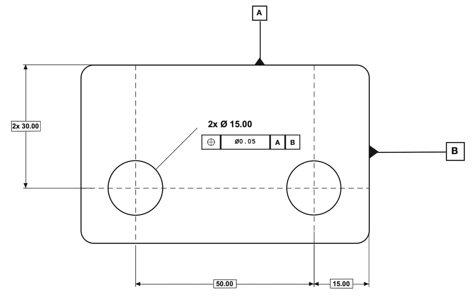
Controls
The location of a feature's axis, centre point or median plane relative to its theoretically exact (basic) position, defined by basic dimensions from datum references. The tolerance zone is a cylinder (for holes/pins), two parallel planes (for slots/tabs) or a sphere (for point features), all centred on the true position.
It is the most widely used GD&T callout in manufacturing.
Example
8 × M6 tapped holes on a hydraulic manifold flange must each fall within Ø0.2mm of their true position to assemble with the mating flange and allow all fasteners to engage simultaneously. At MMC, any bonus from undersize holes adds directly to the allowable zone.
Inspection
Datum & Modifiers
Location is meaningless without a datum reference frame. Typically A|B|C with primary, secondary and tertiary datums establishing all six degrees of freedom.
MMC is most common for bolt patterns — allows bonus tolerance and functional gauging. LMC is used for minimum wall thickness. RFS requires the zone to be met regardless of feature size.
Datum modifiers MMB and LMB are also allowed on the datum references.