Controls
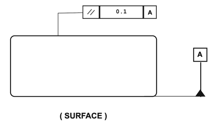
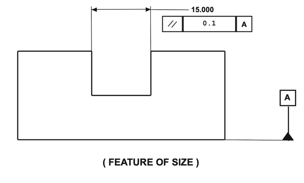
A surface or axis must lie within a tolerance zone oriented exactly parallel to the datum reference. For a surface, the zone is two parallel planes separated by t and parallel to the datum. For an axis, the zone is a cylinder of diameter t whose centreline is parallel to the datum.
Parallelism controls orientation only — it does not control the distance between the controlled feature and the datum.
Example
The two guideways of a lathe bed must be parallel to each other within 0.01mm per 300mm so the saddle does not rack or bind during traversal. Parallelism is also used on parallel bores in engine blocks — if the bores are not parallel, the crankshaft and connecting rods cannot move freely.
Inspection
Datum & Modifiers
Orientation cannot be defined without a reference. The datum establishes the direction from which parallel is measured.
Allowed for features of size (axes, centre planes). Bonus tolerance applies as the feature departs from MMC/LMC. Not valid for flat surface parallelism.