Controls
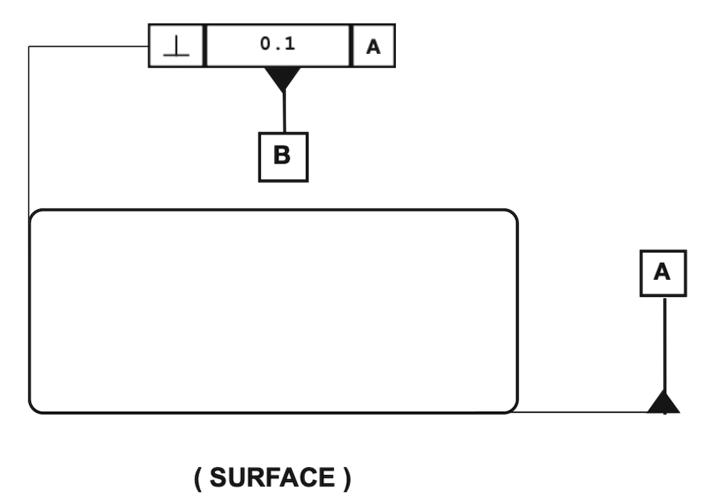
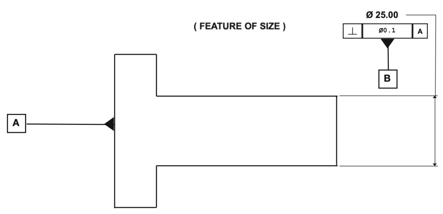
A surface, axis or centre plane must lie within a tolerance zone at exactly 90° to the datum reference. For a surface, the zone is two parallel planes perpendicular to the datum. For an axis, the zone is a cylinder of diameter t whose axis is perpendicular to the datum.
Perpendicularity is the most common orientation control — it governs upright walls, vertical bores, flange faces and pressed-in pins.
Example
A jig bushing pressed into a drill plate must have its bore axis perpendicular to the plate base face within Ø0.05mm. If the bushing is tilted, drilled holes will be angled — compounding position errors across the workpiece. Perpendicularity is also critical on O-ring grooves, sealing flanges and connector housings.
Inspection
Datum & Modifiers
The datum establishes the reference plane from which 90° is measured. Without a datum, perpendicularity cannot be defined.
Allowed for features of size (bores, pins). Bonus tolerance applies as size departs from MMC/LMC. Not valid for flat surface perpendicularity.