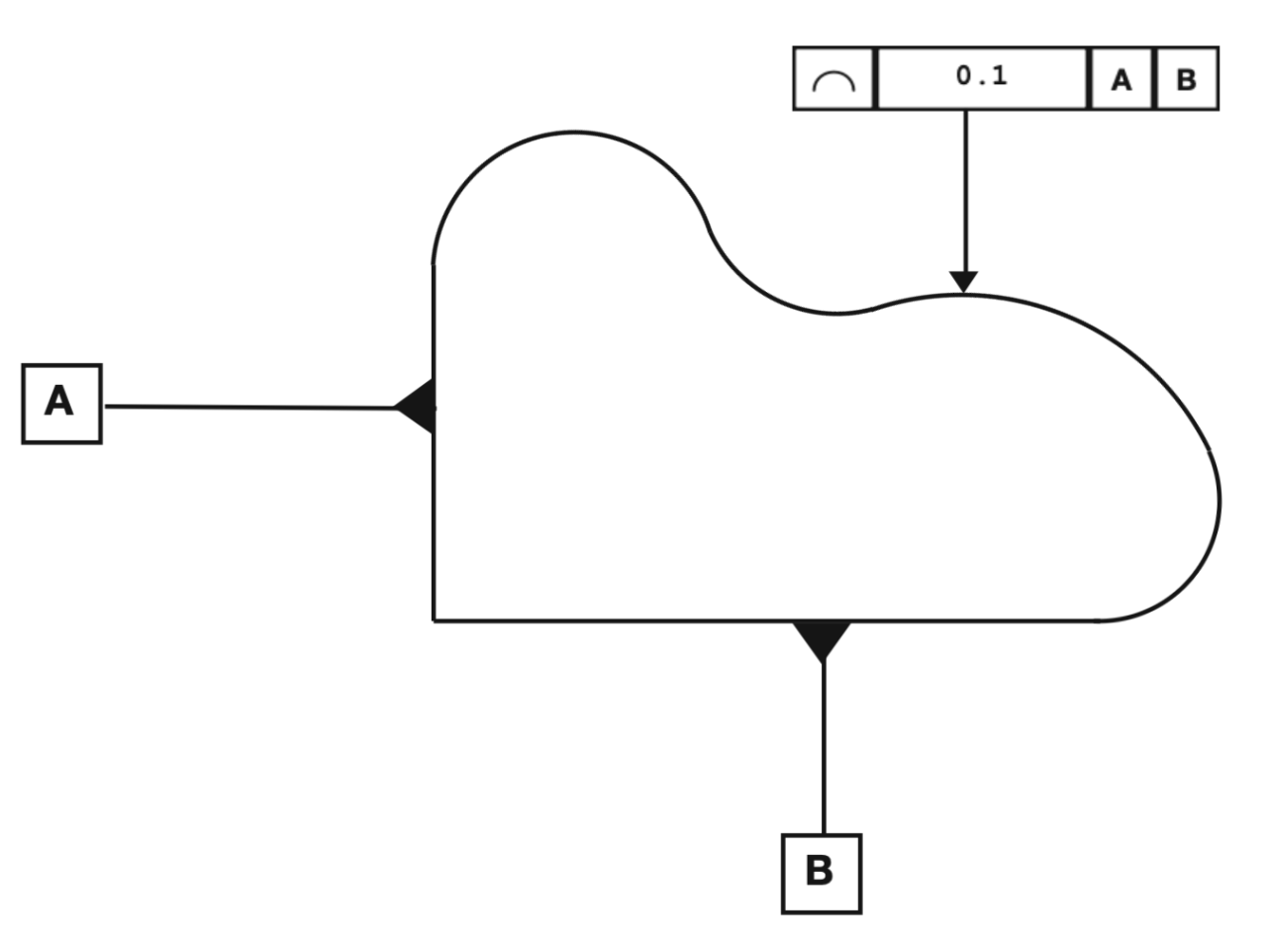
Controls
At any 2D cross-section taken through the part, all surface points must lie within a uniform band of width t centred on the true profile curve. Each cross-section is evaluated independently.
Without datums: controls form only — the profile floats to its best-fit position. With datums: controls the profile's orientation and location relative to the datum frame as well.
Example
A turbine blade must conform to its aerofoil profile within 0.08mm at each radial cross-section to maintain the correct pressure distribution and aerodynamic efficiency. Profile of a line is specified at each inspection slice rather than across the full 3D surface, allowing the blade to be checked section by section.
Inspection
The drawing must specify where each cross-section is taken (e.g. at R=80, R=90, etc. for a blade).
Datum & Modifiers
Without datums: form control only (self-referential). With datums: location and orientation are also controlled. Most production applications use datums.
The U symbol specifies an unequal bilateral tolerance — e.g. the band is offset more to one side of the true profile than the other. Useful for controlled stock allowance.