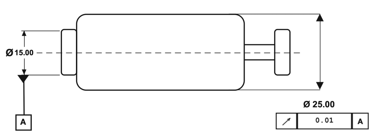
Controls
The total indicator movement (TIM) — also called full indicator movement (FIM) — at any single circular cross-section as the part rotates 360° about the datum axis. The tolerance is the difference between the highest and lowest reading at that one slice.
Circular runout captures the combined effects of eccentricity (centre offset) and out-of-roundness (lobing) in a single reading — but each slice is evaluated independently.
Example
A pump shaft's rotary seal journal must pass circular runout of 0.02mm. If the journal runs out beyond this, the rotating seal lip cannot maintain continuous contact through each revolution, causing intermittent leakage and accelerated lip wear. The journal is checked at multiple axial positions along its length.
Inspection
For face runout (axial runout on a flat face), the indicator is positioned to measure axially while the part rotates.
Datum & Modifiers
The datum axis is the rotation axis — the feature cannot be evaluated without it. Typically a turned diameter or a set of two bearing journals.
Runout is always evaluated regardless of feature size. MMC and LMC do not apply to runout controls.